

HYPERXITE POD VIII

STATIC STRUCTURES
The Static Structures subteam designs the chassis of the Hyperloop pod, with the goal of sustaining the forces from mounting and operating the pod's components, most notably the linear induction motor (LIM). The chassis comprises 10 aluminum square tubes connected using corner connectors and aluminum gussets, and four carbon-fiber cross sections for lateral rigidity. Through SolidWorks, components from other subsystems are integrated into the chassis; expected forces from simulations are used to determine their positioning and mounting method on the pod. Additionally, a carbon fiber fairing is in development to improve the pod's aerodynamics by reducing drag.
PROPULSION
The Propulsion subteam works to design, manufacture, and test the linear induction motor (LIM) to electromagnetically propel the pod. An 18-slot LIM was designed and constructed, capable of over 700 N of thrust with 55 A of current. The goal is to have the pod reach a speed of 45 mph over 200 ft of track. Several key factors of the LIM such as the applied current, the number of windings, and the air gap, greatly affect the LIM's performance and overall thrust generated. COMSOL Multiphysics was utilized to model the electromagnetic properties of the LIM and optimize its design. The Propulsion subteam created a small-scale mini LIM and wound it themselves to validate their COMSOL and analytical models. This mini LIM was then utilized to create a small pod suitable for demonstrating electromagnetic propulsion to a public audience.


DYNAMIC SYSTEMS
The Dynamics subteam is in charge of designing, optimizing, and assembling the suspension system for the pod. Since Pod 8 is propelled by a linear induction motor rather than a wheel-based propulsion system, the underside suspension is no longer necessary to provide additional downforce. The suspensions play a crucial role in stabilizing the pod as it travels along the I-beam track, preventing small bumps on the track from generating large impulses and harming the pod. To mitigate this risk, the Pod 8 suspension system incorporates shock absorbers and springs. The selection of these components was guided by the team's 5-DoF dynamic model created in Simulink, which accurately simulates the pod's motion and enables the team to determine the ideal shock absorbers and springs that minimize deflections.
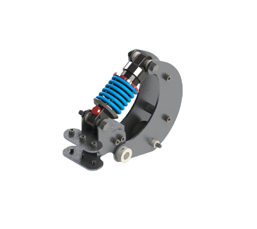
BRAKING
The Pod 8 braking mechanism is a pneumatically-actuated friction braking system. The system utilizes pneumatic actuators to compress high-force gas springs while the pod is running. When the pod is ready to stop, the pneumatic actuators will be released and the gas springs will apply 2700 Newtons of force to decelerate the Pod and produce over 1500 Newtons of braking force. In the case of pneumatic failure, the friction-based failsafe will bring the pod to a complete stop. The focus of this year's braking system is to reduce the width of the braking system from Pod 7 while still maintaining a high braking force. This reduction in footprint is critical to making room for the large linear induction motors and reducing the overall weight of the pod.


PNEUMATICS
The pneumatic system is utilized to engage the braking system, which incorporates an electronic pressure regulator (EPR) that down-steps highly pressurized air from a storage tank. The EPR is equipped with a pressure transducer that links directly to the control valve, enabling closed-loop feedback pressure control to compensate for any pressure fluctuations and regulate downstream pressure. Pressurizing the system compresses the gas springs, allowing the pod to move, until the system is depressurized, in which the brake pads will clamp to the I-beam, creating a failsafe system. A braking test rig aims to evaluate the system's performance in real-life scenarios, providing reliable results and data from a mass flow sensor, such as flow rate, actuation time, and braking force, which are critical in determining the system's performance and validating calculations.
POWER SYSTEMS
The Power Systems subteam is tasked with designing, integrating, and providing sufficient power to the electronic components of the pod. The Powers subteam has designed a custom three-phase inverter to drive the pod’s linear induction motor with current-sensing functionality. Additionally, they have designed a PCB to obtain pressure data and supply adequate voltage to the electronic pressure transducer. Another important component of the pod’s electronic system is the Battery Management System (BMS), which balances the voltages of individual battery cells and reads the state of charge. A control board PCB has been designed to efficiently communicate with the BMS using a CAN transceiver.


Control SystemS
The Controls Systems subteam is responsible for ensuring the safe control of the pod by establishing communication between various sensors and subsystems. They have designed a Finite State Machine (FSM) to model the pod's behavior under every possible scenario, as well as establishing communication between the pod and a host computer through the use of socket communication. A Graphical User Interface (GUI) Control Panel has been created to display important data from pod peripherals during a pod run. Additionally, the Controls subteam has developed a sinusoidal pulse density modulation function that enables the three-phase inverter to convert DC power to AC power for the linear induction motor. They are also creating a custom current sensor for the inverter board using SimpleFOC.